
In 1955, after the murder of Emmett Till in Mississippi, Rod Serling sat down and wrote the most important script of his life.
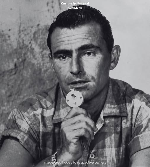
He was a short, intense man with scars on his wrist and knee from his time as a paratrooper in the Pacific during World War II. He had seen what human beings could do to each other when they decided someone was less than human. He had come home from the war not wanting to write comedies or sell products but to use the new medium of television to say something true about the racism and violence he saw moving through his own country.
The script he wrote about Emmett Till — the boy beaten to death in Mississippi for allegedly whistling at a white woman, whose murderers were acquitted by an all-white jury despite their own public confessions — was direct and angry. He called it The Arena. He believed it was the most urgent thing he had written.
He sent it to the network.
The television industry of the 1950s operated on a logic that was simple and cold: the primary purpose of broadcasting was to deliver a satisfied audience to the companies that paid for airtime. Tobacco companies, automotive manufacturers, household goods brands — they funded the programs and they had clear expectations about what those programs should make viewers feel. Anxiety was bad for sales. Moral discomfort was bad for sales. Anything that reminded a viewer, during the comfortable hour they had set aside for television, that their country contained serious injustice was bad for sales.
The network executives read Serling’s script and told him what needed to change.
The story could not be set in the South. The victim could not be Black. They moved the setting to the Wild West in the late nineteenth century and made the victim a white ex-convict. They removed a bottle of Coca-Cola from a scene because a competing beverage company was the sponsor. By the time the changes were complete, the story about a real boy murdered by a real mob in Mississippi had become a western with none of the specificity that made the murder worth writing about in the first place.
Serling stood in the studio and watched the rehearsal. The anger was gone. The truth had been processed into something harmless. He felt a physical revulsion at what had been done to it and at his own participation in allowing it to happen.
He tried again with other material. He wrote about corruption in the Senate. The censors cut everything that sounded like an actual senator making an actual argument. He wrote about hate groups. Sponsors threatened to withdraw their funding. The mechanism was consistent and effective: any language that connected to the real world in a way that might make a viewer uncomfortable was removed, and the writers who kept submitting such material were educated about the economics of the industry until they either stopped or left.
Serling was not a man who was inclined to leave. But he was also, by his own account, beginning to feel like a coward. Every time he followed the rules, every time he allowed the scripts to be sanitized until they said nothing, he understood more clearly what he was participating in.
He went home and looked at his shelves. He read science fiction. He read fantasy. He began to understand something about the men with the red pens: they were literal. They scanned for specific words — the names of political parties, the vocabulary of contemporary social conflict. They were not looking for metaphors. They did not audit the politics of Martians. They did not track the ideological implications of stories about robots.
He decided to build a Trojan horse.
He pitched a new anthology series. He described it as a collection of fantasy tales — spaceships, aliens, time travel, the supernatural. The executives heard escapism. They heard children’s entertainment and dreamer programming. They heard nothing that would threaten a sponsor’s quarterly sales figures. They approved it. The show would be called The Twilight Zone.
For five seasons beginning in 1959, Serling appeared on American television in a black suit, holding a cigarette, introducing stories about the impossible. The episodes ran in front of millions of viewers. The sponsors sold their products in the commercial breaks. The network executives watched the ratings with satisfaction.
What they were not watching carefully enough was the content.
When Serling wanted to write about Cold War paranoia — about neighbors turning on neighbors, about the way fear could transform ordinary people into a mob willing to destroy anyone they decided to suspect — he did not write about the Cold War. He wrote about a street where the lights flicker inexplicably and the residents, terrified, begin to accuse each other of being aliens. The sponsors did not cut a single line. The episode, “The Monsters Are Due on Maple Street,” aired in 1960 and was watched by millions of people who understood exactly what it was about.
When he wanted to write about conformity — about the horror of a society that punishes anyone who looks different, that defines beauty as whatever the majority resembles and treats deviation as illness requiring correction — he did not write about conformity. He wrote about a woman in a hospital, her face entirely bandaged, waiting to learn whether the surgery had made her look like everyone else. The reveal, when it came, showed a face that was conventionally beautiful surrounded by faces that were not. The episode, “Eye of the Beholder,” aired in 1960. The sponsors sold their cigarettes during the commercial breaks without understanding that the program had just been a meditation on the relationship between majority aesthetics and state power.
The mechanism was clean and durable. The censors who had removed the bottle of Coca-Cola from his Till script and moved his Southern lynching story to the Wild West were looking for explicit language. Serling had stopped using explicit language. He had wrapped everything in masks — spaceships, bandages, aliens on a hill — and then transmitted it directly into the living rooms of the country that the networks had told him was too fragile to hear the truth.
He was, by the network’s own accounting, one of the most successful television writers of his era. The show he was laughing at them with was one of their best performers.
Rod Serling died in 1975 at fifty years old, following open-heart surgery. The Twilight Zone has never been off the air in the decades since — it runs in syndication, has been revived multiple times, and is taught in schools and universities as a record of what serious social criticism looks like when it is forced to find a form that the institutions controlling its distribution cannot read clearly enough to stop.
What the executives approved as escapism has lasted sixty-five years. The scripts they sanitized are mostly forgotten.
For those who have ever been prevented from saying a true thing directly and had to find another way to say it — Rod Serling’s Trojan horse is a record of what that looks like when the indirect route is the only one available and the writer is skilled enough to use it.
He put a mask on the truth. The truth got through.
What would you say if you were not allowed to say it directly — and what form would you need to put it in for the people controlling the door to wave it through?